 Kia Forte: Engine And Transaxle Assembly Removal
Second generation YD (2014-2018) / Kia Forte TD 2014-2018 Service Manual / Engine Mechanical System / Engine And Transaxle Assembly / Engine And Transaxle Assembly Removal
|
|
| 1. |
Remove the engine cover.
|
| 2. |
Remove the battery and battery tray.
(Refer to Engine Electrical System - "Battery")
|
| 3. |
Remove the engine room under cover.
(Refer to Engine And Transaxle Assembly - Engine Room Under Cover")
|
| 4. |
Drain the engine coolant.
(Refer to Cooling System - "Coolant")
|
| 5. |
Disconnect the radiator upper hose (A).
|
| 6. |
Disconnect the radiator lower hose (A).
|
| 7. |
Recover the refrigerant and then remove the high pressure pipe
and low pressure pipe.
(Refer to Heating, Ventilation Air conditioning -"Compressor")
|
| 8. |
Remove the transaxle wire harness connectors and control cable
from the transaxle.
(Refer to Manual Transaxle System - "Manual Transaxle")
(Refer to Automatic Transaxle System - "Automatic transaxle")
|
| 9. |
Disconnect the brake booster vacuum hose (A) and the heater hoses
(B).
|
| 10. |
Disconnect the fuel hose (A) and the purge control solenoid valve
(PCSV) hose (B).
|
| 11. |
Remove the engine wirings from the engine room.
|
| 12. |
Remove the front muffler.
(Refer to Intake And Exhaust System - "Muffler")
|
| 13. |
Remove the roll rod bracket (A).
|
| 14. |
Remove the roll rod mounting support bracket (A).
|
| 15. |
Remove the sub frame.
(Refer to Suspension system - "Sub frame")
|
| 16. |
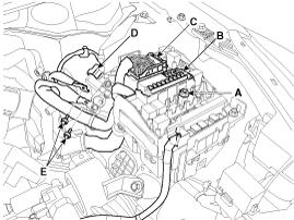
Disconnect the ground cable (A).
|
| 17. |
Remove the engine mounting support bracket (B).
|
| 18. |
Disconnect the ground line (A).
|
| 19. |
Remove the service cover (A), and then slowly loosen the transaxle
mounting bolts (B).
|
| 20. |
Remove the engine and transaxle assembly by lifting vehicle.
|
 Engine Mounting Removal and Installation
Engine mounting bracket
1.
Install the jack to the edge of oil pan to support the engine.
...
 Engine And Transaxle Assembly Installation
Installation is in the reverse order of removal.
Perform the following :
Х
Adjust shift cable.
Х
Adjust throttle cable.
Х
...
See also:
Component Location
1. Quarter fixed glass
...
Multimedia Jack Removal
1.
Disconnect the negative (-) battery terminal.
2.
Remove the floor console assembly.
(Refer to Body - "Floor Console Assembly&quo ...
Resetting The Sunroof
Whenever the vehicle battery is disconnected or discharged, or you use
the emergency handle to operate the sunroof, you have to reset your sunroof
system as follows :
1.
...
Copyright © www.kifomanual.com 2014-2025


